
Consultation Hotline
+1 (302) 618-8777
+1 (302) 618-8777
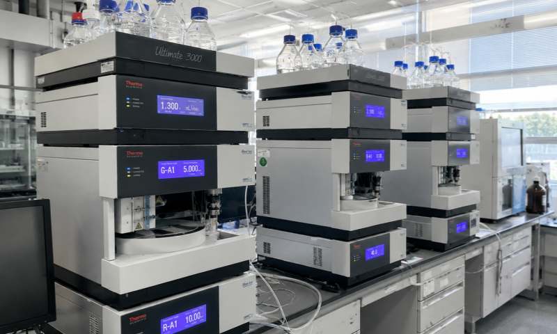
Shimadzu gas chromatography (GC) systems are widely used in analytical laboratories for pharmaceutical analysis, environmental testing, petrochemical research, food safety, and chemical analysis. A common problem encountered during GC operation is that no peaks appear after sample injection, even though the instrument seems to run normally. This issue can be caused by various factors, including sample preparation problems, injection system failures, carrier gas issues, column problems, detector malfunctions, and data acquisition errors.
A systematic troubleshooting approach can help quickly identify the cause and restore normal operation. This article provides both a simple overview and a detailed analysis of the possible reasons and solutions for a Shimadzu GC system showing no peaks after injection.
When a Shimadzu GC shows no peaks after injection, the problem usually comes from five major areas:
The first thing to check is whether the sample actually contains detectable compounds.
Possible causes:
Sample concentration is too low.
Sample preparation is incorrect.
The sample was not injected properly.
The sample has degraded or evaporated.
The wrong vial was selected.
Solution:
Prepare a new sample with a higher concentration.
Check the sample information and vial position.
Inject a standard sample to confirm whether the instrument works properly.
The injector is one of the most common causes of missing peaks.
Possible problems include:
Empty syringe or incorrect syringe operation.
Autosampler failure.
Blocked injection needle.
Septum leakage.
Incorrect injection volume.
Wrong injection mode settings.
For example, in split injection mode, if the split ratio is set too high, most of the sample may be vented out and the amount entering the column becomes too small to detect.
Solution:
Check syringe movement and injection sequence.
Verify injection volume settings.
Reduce the split ratio if necessary.
Replace damaged septum.
Clean or replace the injector liner.
The carrier gas transports sample components through the GC column. Without proper carrier gas flow, compounds cannot reach the detector.
Possible causes:
No carrier gas supply.
Gas cylinder empty.
Incorrect pressure setting.
Gas leakage.
Electronic flow control (AFC/EPC) malfunction.
Solution:
Check carrier gas pressure.
Confirm gas supply is sufficient.
Perform a leak test.
Verify the flow rate using Shimadzu GC software.
The GC column is responsible for separation. Column problems can result in missing peaks.
Possible causes:
Column installation error.
Column contamination.
Column damage.
Incorrect column temperature program.
Excessive column bleeding.
Solution:
Check column connection at injector and detector.
Confirm column dimensions and installation depth.
Condition the column.
Replace the column if it is damaged.
If the sample reaches the detector but no signal is generated, the detector may be the problem.
Common detector issues:
FID flame not ignited.
Incorrect detector temperature.
Gas supply problems.
Detector contamination.
Signal acquisition failure.
Solution:
Check detector status.
Confirm flame ignition for FID.
Verify hydrogen, air, and makeup gas flow.
Clean the detector if necessary.
The first step is to confirm that the sample was injected successfully.
For manual injection:
Verify that the syringe contains sample.
Confirm correct injection technique.
Ensure the syringe needle enters the inlet properly.
For autosampler injection:
Check autosampler status.
Confirm vial position.
Verify that the autosampler needle moves correctly.
Check whether the syringe draws and dispenses liquid.
A failed injection can result in a completely flat chromatogram.
Shimadzu GC systems such as Shimadzu GC-2030 Gas Chromatograph allow detailed control of injector parameters.
Important parameters include:
If the injector temperature is too low:
The sample may not vaporize completely.
Compounds may remain in the liner.
Peak response becomes very weak or disappears.
Recommended action:
Confirm the injector temperature matches the analytical method.
Check heater performance.
The split ratio controls how much sample enters the column.
Example:
A split ratio of 100:1 means only about 1% of injected sample enters the column.
If the split ratio is accidentally increased:
Peaks may become extremely small.
Low concentration compounds may disappear completely.
Recommended action:
Reduce the split ratio.
Test with splitless injection mode.
The liner plays an important role in vaporization and transfer.
Problems include:
Contamination.
Active sites.
Broken glass wool.
Incorrect liner type.
Symptoms:
Reduced peak intensity.
Poor reproducibility.
Missing peaks.
Solution:
Replace the liner.
Replace glass wool.
Use a liner suitable for the sample type.
Shimadzu GC instruments use advanced flow control systems to maintain stable carrier gas conditions. Any abnormality can affect peak formation.
Check:
Insufficient pressure can prevent sample movement through the column.
Check:
Cylinder pressure.
Regulator condition.
Gas line connection.
Leaks are common around:
Injector connections.
Column fittings.
Gas tubing.
A leak may cause:
Longer retention times.
Low sensitivity.
No peaks.
Solution:
Perform leak testing.
Tighten fittings carefully.
Replace damaged ferrules.
Even when injection is correct, incorrect GC temperature settings can prevent peak detection.
Possible problems:
The sample may remain condensed at the column entrance.
This may cause excessive column bleeding and background problems.
If the temperature program does not match the method:
Target compounds may not elute.
Peaks may appear outside the expected time window.
Solution:
Review the GC method.
Compare with a validated analytical method.
Run a standard mixture.
The flame ionization detector (FID) is commonly used in Shimadzu GC systems.
Check:
Hydrogen flow.
Air flow.
Makeup gas flow.
Flame ignition status.
If the FID flame is off:
The chromatogram will show no peaks.
The baseline may remain flat.
Solution:
Ignite the flame.
Verify gas supply.
Clean the jet if contaminated.
For thermal conductivity detectors:
Possible causes:
Incorrect filament temperature.
Reference gas problem.
Detector contamination.
Solution:
Check detector parameters.
Confirm stable gas flow.
Sometimes the instrument works correctly but the software does not display peaks.
Possible reasons:
Incorrect signal channel selected.
Detector signal not connected.
Wrong data acquisition settings.
Integration parameters too strict.
Solution:
Check chromatogram channel.
Confirm detector signal recording.
Adjust integration settings.
Run a test injection.
For efficient diagnosis, follow this order:
Confirm sample quality.
Check injection operation.
Verify injector temperature and split ratio.
Check carrier gas supply and flow.
Inspect column installation.
Confirm detector operation.
Check software acquisition settings.
Inject a standard sample for verification.
This sequence avoids unnecessary replacement of expensive components.
A Shimadzu GC system showing no peaks after injection can be caused by simple issues such as an incorrect sample injection or complex problems involving gas flow, columns, detectors, or electronic control systems. The most effective troubleshooting method is to inspect the entire analytical pathway—from sample introduction, vaporization, separation, detection, to data processing.
Regular maintenance, including injector cleaning, column conditioning, gas leak inspection, and detector performance checks, can significantly reduce the occurrence of no-peak failures. By following a systematic diagnostic process, most Shimadzu GC peak loss problems can be quickly identified and resolved, ensuring reliable analytical performance and extending instrument service life.