Consultation Hotline
+1 (302) 618-8777
+1 (302) 618-8777
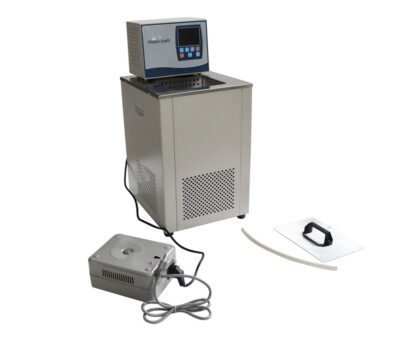
Low-temperature cooling circulators maintain precise temperature control by circulating a heat transfer fluid through an external system. The core mechanism involves a refrigeration circuit that extracts heat from the circulating fluid, a heating element for temperature elevation when needed, and a circulation pump that moves fluid through the system. Most modern units utilize PID-controlled compressors and PT1000 temperature sensors to achieve temperature stability within ±0.1°C.
Compressor System: Often utilizes cascade or single-stage refrigeration with environmentally friendly refrigerants (R404A, R407C, R134a)
Circulation Pump: Typically magnetically coupled or canned motor pumps providing 2-15 L/min flow rates
Heat Exchanger: Brazed plate or shell-and-tube design requiring specific fluid compatibility
Control System: Microprocessor-based with multiple safety interlocks
Fluid Reservoir: Typically 5-20 liters with expansion capability
|
Application Temperature Range |
Recommended Fluid Type |
Key Properties |
Replacement Interval |
|---|---|---|---|
|
-40°C to +100°C |
Silicone-based oil |
Low viscosity at cold, high flash point |
12-18 months |
|
-20°C to +80°C |
Ethylene glycol/water mix (50/50) |
Good heat transfer, cost-effective |
6-12 months |
|
-80°C to +100°C |
Specialized synthetic fluids |
Ultra-low viscosity, wide range |
12 months |
|
-10°C to +150°C |
Fluorinated fluids |
Chemically inert, non-flammable |
18-24 months |
Weekly Inspection:
Visual check for discoloration or particulate matter
pH measurement (6.5-8.0 for aqueous solutions)
Viscosity check at 20°C (should not exceed 150% of new fluid viscosity)
Monthly Testing:
Water content analysis (<200 ppm for non-aqueous fluids)
Bacterial growth testing for aqueous solutions
Corrosion inhibitor concentration verification
Fluid Replacement Procedure:
Completely drain old fluid through bottom valve
Flush system with compatible cleaning solution
Triple rinse with deionized water (for aqueous systems)
Filter new fluid through 5-micron filter during filling
Degas by running at 40°C for 2 hours with reservoir open
Pre-Start Checklist:
Verify fluid level between MIN and MAX markers
Check for visible leaks or corrosion
Ensure all external connections are secure
Confirm ambient temperature between 15-30°C
Verify adequate clearance (minimum 30 cm on all sides)
Power-Up Protocol:
Engage main power switch, wait 30 seconds for controller initialization
Set temperature 5°C above ambient before activating cooling
Gradually approach target temperature (max 5°C/minute change)
Allow 20-30 minutes for temperature stabilization
Performance Verification:
Confirm set point and actual temperature within 0.5°C
Check pump pressure (typically 1-3 bar)
Verify flow rate meets equipment requirements
Monitor for unusual noises or vibrations
Cooling Deactivation:
Gradually increase temperature to 20°C (maximum 3°C/minute)
Continue circulation for 15 minutes after reaching ambient
Turn off cooling system first, then pump after 5 minutes
System Preservation:
For extended shutdown (>1 week), drain fluid and purge with dry nitrogen
Close all valves and cap openings
Place "Out of Service" tag with date and reason
Cover unit to prevent dust accumulation
Flow Rate Verification: Measure with calibrated flow meter, compare to specification
Temperature Stability: Record variation over 1 hour, should be <0.2°C
Pressure Drop Analysis: Compare inlet/outlet pressures, investigate >20% increase
Compressor Cycling: Monitor on/off frequency, excessive cycling indicates issues
Pump Seal Area: Check for weeping or crust formation
Electrical Connections: Verify tightness, look for discoloration
Condenser Fins: Remove dust with soft brush or low-pressure air
Hose Connections: Check for cracks, stiffening, or leaks
Reservoir Condition: Inspect for corrosion or sediment accumulation
Air-Cooled Condensers:
Clean fins with fin comb and compressed air (<2 bar)
Straighten any bent fins
Verify fan operation and bearing condition
Fluid Circuit Inspection:
Check for mineral deposits or scaling
Perform acid cleaning if pH indicates corrosion
Verify all isolation valves operate smoothly
Bearing Inspection: Check for excessive play or noise
Shaft Seal Replacement: Proactive replacement every 6,000 operating hours
Coupling Alignment: Verify alignment with straight edge and feeler gauge
Motor Current Draw: Measure and compare to nameplate rating
Test high-temperature cutoff at 5°C above maximum operating temperature
Verify low-fluid level shutdown function
Check flow switch operation by temporarily restricting flow
Confirm pressure relief valve operation (if equipped)
Compressor Oil Analysis: Check acidity (<0.5 mg KOH/g) and moisture (<50 ppm)
Refrigerant Charge Verification: Compare high/low side pressures to specifications
Filter-Drier Inspection: Replace if moisture indicator shows wet condition
Leak Detection: Electronic leak check of all refrigerant connections
Temperature Sensor Verification: Compare to NIST-traceable reference thermometer
Controller Calibration: Adjust if deviation exceeds ±0.5°C
Display Verification: Confirm digital readout matches controller output
Alarm Function Test: Simulate all alarm conditions
Fluid System Overhaul:
Complete fluid replacement with system flush
Replacement of all hose connections and seals
Pump disassembly, inspection, and bearing replacement
Heat exchanger chemical cleaning
Refrigeration System Service:
Oil change and filter replacement
Receiver inspection and cleaning
Expansion valve calibration
Complete leak test and refrigerant recharge
Electrical System Inspection:
Megger test motor windings (>100 MΩ)
Contactor contact inspection and cleaning
Grounding verification (<0.5 Ω resistance)
Control board inspection for capacitor health
Temperature Uniformity Test: ±0.5°C across operating range
Cooling Capacity Verification: Measure at multiple set points
Flow Rate Certification: At various back pressures
Noise Level Measurement: Should be <65 dBA at 1 meter
Energy Consumption Verification: Compare to specifications
Symptoms: Slow temperature drop, inability to reach set point
Possible Causes:
Dirty condenser reducing heat transfer
Low refrigerant charge
Excessive system load
Improper fluid viscosity
Pump failure or reduced flow
Corrective Actions:
Clean condenser with approved methods
Check and recharge refrigerant
Verify external system heat load
Replace with proper viscosity fluid
Check pump impeller and motor
Symptoms: Temperature oscillations >1°C
Diagnostic Approach:
Check PID settings - may need retuning
Verify proper fluid volume in system
Check for air in system (bleed if necessary)
Inspect temperature sensor placement
Verify pump is providing consistent flow
Solutions:
Perform auto-tune function
Adjust fluid to proper level
Reposition sensor in flow stream
Replace pump if inconsistent
Thermal Protection: Insulated gloves for temperatures below 0°C
Chemical Protection: Appropriate gloves and eye protection for fluid handling
Electrical Safety: Lock-out/tag-out procedures during maintenance
Hearing Protection: Required for pumps exceeding 80 dBA
Fluid Spill Response: Contain with absorbent materials, proper disposal
Electrical Fire: Use Class C fire extinguisher, never water
Refrigerant Leak: Ventilate area, use appropriate respirator
System Overpressure: Evacuate area, let pressure relief valve function
Set temperature 5-10°C above minimum required
Implement scheduled shutdown during non-working hours
Maintain clean heat exchange surfaces
Ensure proper fluid level and quality
Use variable speed pumps when possible
Install economizer for free cooling when ambient <10°C
Add insulation to exposed piping
Implement heat recovery where applicable
Upgrade to high-efficiency motors
Install variable frequency drives on pumps
Daily Log: Temperatures, pressures, fluid levels, observations
Maintenance Records: All services, parts replaced, fluid changes
Calibration Certificates: Temperature sensors, pressure gauges
Performance Validation: Quarterly and annual test results
Training Records: Operator and maintenance personnel certifications
Trend analysis of compressor run times
Power consumption monitoring
Temperature stability over time
Fluid degradation rates
Component failure history
Proper refrigerant handling per EPA Section 608
Fluid disposal according to local regulations
Energy efficiency standards compliance
Noise level regulations (<70 dBA typically)
ASHRAE standards for refrigeration systems
ISO 9001 for quality management
CE/UL certification requirements
Local electrical and building codes
Implementing this comprehensive maintenance and operational program typically achieves:
30-40% extended equipment lifespan
20-30% reduced energy consumption
50% reduction in unplanned downtime
Consistent temperature control within ±0.2°C
Compliance with all regulatory requirements
Proper management of low-temperature cooling circulators ensures reliable performance for sensitive applications in pharmaceutical manufacturing, chemical processing, materials testing, and research laboratories, while optimizing operational costs and minimizing environmental impact.